Hobby projects
One of my hobbies as a kid was to take things apart and then put them back together. Without knowing it I was preparing myself for all the making/hacking goodness that is around us today. I'm always trying out new things and this lead to some projects that we're featured in Wired magazine, Hackaday and even occasionally in the papers (like AnyKey). Ofcourse also many failures but I tend not to document those as much ;). Here are some higlights of those successful hobby projects:
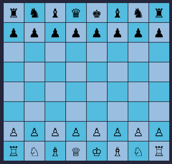
Nano Chess
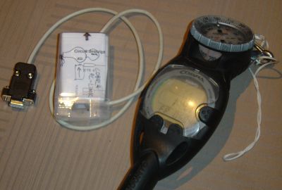
Cobra Suunto computer interface
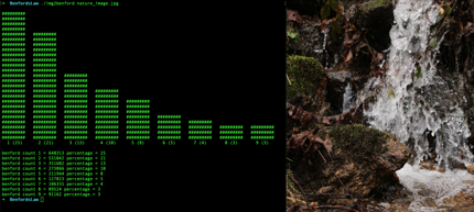
Benford's law for images
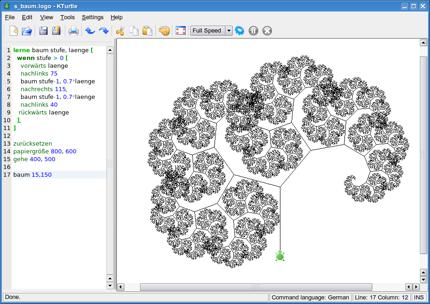
WSBasic and KTurtle

DC Motor Controller
Wii controller hack
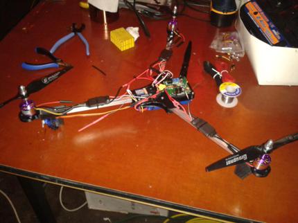
3D printed Tri Copter
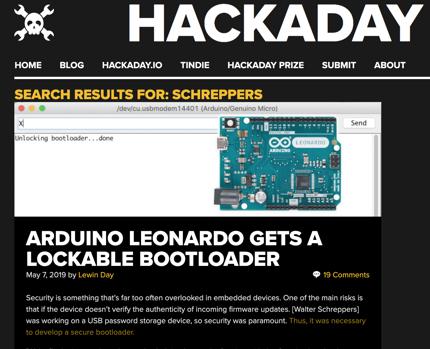
Arduino Lockable Bootloader
Led Clock and Microchip RCD programmer
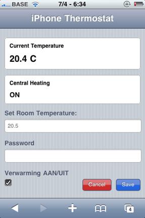
IOT web thermostat
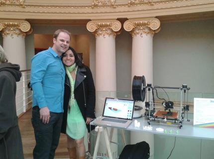
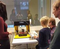
3D Printing Workshops
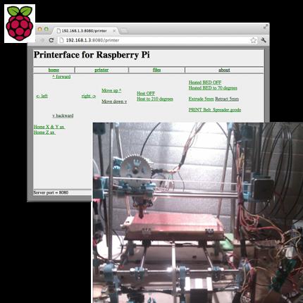
Printerface IOT for 3D Printers
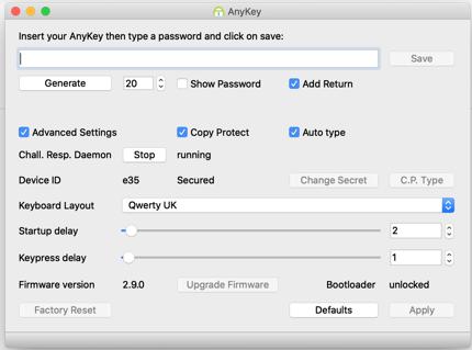
AnyKey Configurator Desktop Software macOS, Windows, Linux
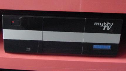
MythTV DIY Tivo
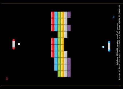
ArkaPong
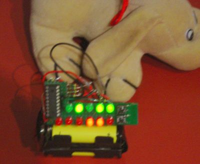
BeeBot
Foldable 3D Printer
Foldable 3D Printer
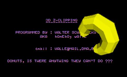
z-clipping
AKA
Ninja 3D Slicer in 1998
AKA
Ninja 3D Slicer in 1998
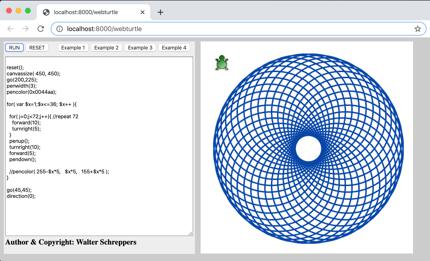
WebTurtle